Monitoring and controlling relative humidity is important for humans health. Too low or too high humidity feels uncomfortable, but most importantly high moisture is a factor for growing mold in your home, which could be health threatening (according to EPA and CDC). I will not go into details on how to control humidity. Instead I’ll describe what motivated me to design and create my own temperature and humidity sensor which reports its readings every minute to a central Linux server.
")


The main requirements for my design were the following:
- Affordable price, as I wanted to install four sensors.
- Great accuracy both for temperature and humidity readings.
- Over-the-air communication, as I wanted to be able to install a sensor even in my bathroom, where I can’t run data or power wires. Support for wired communication too, so that we can reduce the overall price by not installing the wireless module.
- Data logging to a computer, because both temperature and humidity change with time, for example when you sleep in the room, and you can’t look at a mechanical temperature or humidity meter every minute, in order to write down the results.
- Battery operated, in order to avoid any wiring.
- Open-source hardware and software toolchain, so I chose Atmel AVR microcontrollers. I got sick of Microchip and their commercial C compilers.
- To have fun with electronics but at the same time create the device as fast as possible, as free time turned out to be a pretty limited resource recently.
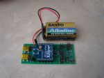
I managed to accomplish most of the requirements I set with two exceptions: the device operates only a month on batteries, and cumulatively I spent almost a week to design, solder, develop the firmware, and test the device. Now all the sensors operate from a wall-plug power adapter, and my hunger for environmental control in my house is satisfied.
I’ll now try to describe the whole process and the reasons behind my engineer decisions. Note that I’m an amateur hobbyist.
Idea and requirements
I wrote down all my thoughts in a text editor. Then re-designed all the sticky notes into requirements, and did so a few more times, in order to finally decide what I want to design and not get distracted by new random ideas in my head.
Power supply
I wanted the device to be able to operate both via USB, and thus be powered by 5V, as well as to be powered by an accumulator or a battery with an input voltage up to 12V, so that it could be used in a car too. I put a polarity protection diode D1 in series with the power line, so that an accidental polarity mismatch doesn’t burn out the power regulator. Such a protection diode must have very low voltage drop and thus low power loss, and the Schottky diode 1N5819 seemed like a good match.
Operating from a battery also means that the voltage regulator must be extremely efficient and with a low bias current consumption, which means that it should draw almost nothing while there is nothing connected to it at its output as a load. Most battery operated devices “sleep” during most of their life cycle, so their consumption is close to zero. I used the ultra low-dropout fixed voltage regulator LP2986-33, marked as U1 in the schematics. The whole circuit operates at 3.3V because of the XBee wireless modules, and also because operating at a lower voltage usually gives lower power consumption.
Since we can have two different power sources, there must be a way to choose which one is active. You can switch between the power sources using the PWR_SELECT jumpers.
Wired communication via USB
I wanted to have the option to use the sensors by directly connecting them to a computer. This way we could save the money for an XBee wireless module. I used the classical USB-to-Serial solution FT232R, which is also quite inexpensive and requires almost no external components. You can see it in the schematics as U2. Note that the I/O lines of FT232R must be configured to operate at 3.3V too. This is done by connecting pin 17, which is the internal 3.3V regulator of FT232R, to pin 4. The internal 3.3V regulator is not used for anything else, and in theory I could have powered the I/O lines, pin 4, directly from the main voltage regulator U1.
")
Wireless communication
The XBee modules is something I wanted to play with for a long time. They seem very easy to work with and are packed with all kind of features. Though in my case I’m not using almost any of them, not even the AES encryption which could secure the data channel. I’m using the Series 1 XBee low-power embedded RF modules (XB24), which have a power of 1 mW and 30 m indoor range. There are many comments in Internet that the indoor range of the XBee modules is poor and I can confirm that. The range really depends on what the signal must travel through. Sometimes you lose the link even through one wall, sometimes it can go through a few walls. The XBee & XBee-PRO OEM RF Module Antenna Considerations is a great article by the XBee manufacturers. After all, probably by using such a low-power module, we shouldn’t expect so great results. It works well in my apartment though — all rooms report to the central XBee module successfully. On the server’s side, the receiver, I first had an XBee with chip antenna, which I replaced with an XBee-PRO with whip antenna. This made no difference.
Wiring the XBee module is very easy. It requires no external components. If you read the PDF datasheet, you’ll see how many great features an XBee has. I’m using only three of them:
- Sleep mode — the microcontroller puts the XBee to sleep by controlling the SLEEP_RQ pin 9.
- Networking addressing — each XBee is configured with a unique address, so that the receiver on the server side knows which reading belongs to which sensor probe.
- API operation — the receiver XBee module operates in an API mode, which is a frame-based protocol that provides greater flexibility and more control. For example, besides the received data payload, an API frame gives information about the sender’s address and the signal quality.
Temperature and humidity sensor
I wanted to interface the sensor directly using a digital protocol, so that we can minimize the ADC stuff and errors. The SHT11 turned out to be the sensor I was looking for:
- Relative humidity accuracy: +/- 3% in the range 20% to 80% RH. The sensor comes fully calibrated.
- Temperature accuracy: +/- 1.5 degrees Celsius in the range -15 to +65 degrees Celsius.
- Digital two-wire interface.
- Very low energy consumption: 80uW (at 12bit, 3V, 1 measurement/s).
The SHT11 is a bit pricey but works very easily and accurately out of the box, so I decided to go with it. There is a very good alternative at Sparkfun — the RHT03 humidity and temperature sensor (also known as “RHT-22”). There were some contradictive comments by Sparkfun users — some say it works very well, some doubt its accuracy. I haven’t tried it but have left space JP7 on the current board, so that at some later time I could solder one RHT03 and use it with the existing schematics.
One note about the SHT11 two-wire interface. Definitely use a pull-up resistor on the DATA wire, as advised in the PDF! I tried to do some magic by the microcontoller and failed. With the exception of the pull-up resistor, everything else worked with no other problems with the SHT11 sensor. The manufacturer Sensirion provides Sample code for the SHTxx sensors which turned out to be very useful. I was able to re-code it for the AVR GNU C compiler in a couple of minutes.
The CRC calculation got me a bit confused. There are multiple different ways to calculate a CRC checksum, and they all provide different results. Each CRC calculation depends on the selected CRC polynomial, which is something like a bit-mask that defines the algorithm for the CRC calculation. After lots of struggle, I finally found an excellent Online CRC Calculation web wizard, which also includes a hardware implementation example, and sample C and VERILOG implementations, which you can copy-paste in your program. Thank you Kay Gorontzi!
Microcontroller
Initially I worked with ATmega8. Then I switched to ATmega168 because of the much lower power consumption. I could have used any other Atmel AVR microcontroller which has USART, internal oscillator, and sleep mode. Though ATmega8 or ATmega168 are always available in my local electronics shop, so I chose one of them. Besides the lower power consumption, ATmega168 has one other major advantage for my application — the watchdog timer can wake the chip from sleep mode and directly execute an interrupt, thus not re-starting the program from the very beginning.
Firmware
I’m working on Windows 7 64-bit and used a USBasp programmer to download the code into the microcontroller. The whole development toolchain is packaged into the WinAVR suite. It includes the AVR GCC compiler and the avrdude programmer. I also downloaded a sample Makefile which makes compilation and firmware download easy.
The main loop of the program does two tasks — measures and displays the readings over the serial port (which goes to the USB or over-the-air via XBee), and sleeps for about 60 seconds. As already mentioned, I use the new feature of ATmega168 which allows for the Watchdog timer to generate an interrupt, which wakes the chip from sleep mode. This is very handy as it allows you to continue the program at the point where you put it to sleep. The sleep mode was something new for me; there are some URLs in the source code which show what online articles helped me to master it. Note that the XBee RF transmitter is also put into sleep mode, in order to save battery.
Data collector
All the sensor readings are collected to a Linux server over-the-air. I use an XBee Explorer USB by Sparkfun to connect the XBee receiver with the Linux server. The XBee is seen as a serial device on the Linux box. The frame protocol of the XBee API is easy to understand and I implemented a Perl script to parse it. Here is a sample reading which is received from one of my wireless sensors (0x0001 is the address of the probe standing outside of my apartment):
[Mon Dec 26 17:32:11 2011] RX_packet: source=0x0001, rssi=-55dBm (opt=0x00): 4.24;69.04
As you can see, now it’s winter here — 4.24 degrees Celsius temperature; 69.04% relative humidity (RH).
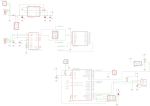
Board design
Both the schematics and PCB board were designed using Eagle PCB by CadSoft. This is a great piece of software. Most PCB factories accept Eagle board files directly. You’ll find my Eagle files in the Resources section at the end of this article.
Lessons learned
There are a few things which I discovered only once I already built and tested the schematics:
- Battery-operated devices are hard to design — in theory my sensors were supposed to last for about 3 months with a 9V battery. In practice only one of them lasted for a month, the others – for a week.
- Electronics components, boards and/or assembly could differ a lot — see above. Also one of the SHT11 sensors is sometimes giving CRC errors.
- XBee indoor range is not excellent.
- Research and development takes a lot of time, usually 2x or 3x the time you planned. Furthermore, building something with love takes even more time, but in the end it pays off with great results and satisfaction.
- You can create an electronics device with a lower price than what is currently offered on the marked. But this has its price too — your time, and you get no guarantee whatsoever.
I had different plans for this blog article but it got so lengthy that I wrote it in four different days (and it’s Christmas now). The main idea was to sketch the device and all its components, and to show that they can work together as a finished product. If there is any interest by other people, I’m happy to answer to any questions.
Happy holidays and best of luck in 2012!!! 🙂
Resources:
