I have been running a Zigbee network with 20 Aqara & IKEA devices for almost two years now. The coordinator is a Raspberry Pi 400 server with a ConBee II USB dongle. It worked more or less flawlessly with very few issues until recently. I had to reboot the coordinator server in order to migrate its root file system from an SD card to a USB-connected SSD drive.
Once I rebooted the coordinator server, almost half of the devices couldn’t reconnect to the network. I upgraded the Zigbee2MQTT daemon, which bridges Zigbee to MQTT events but this didn’t help. A few more restarts didn’t help either. There are plenty of comments on the Internet that the Zigbee USB dongles aren’t stable and some users suggested that the USB port of the Raspberry Pi may be to blame, because it couldn’t supply enough (stable) power. This made sense and I purchased an active USB 3.0 hub with external power supply, which is especially designed for power hungry USB devices like HDDs, etc. Once I plugged in the ConBee II USB dongle into the active powered USB 3.0 hub, my Zigbee network started working again flawlessly!
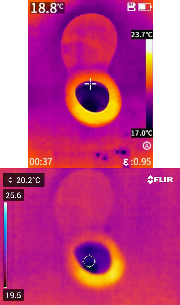
There was only one more minor issue. While the network was incomplete I tried to remove and then re-pair an Aqara sensor, which didn’t work. This is something that other people are experiencing, too. Even after the Zigbee network was stable again, I couldn’t re-pair the sensor. I brought it close to the coordinator, the LED of the sensor was blinking as expected during re-pair but nothing was registered by the coordinator. Finally, I suspected that the battery of the sensor was too weak and couldn’t provide enough power for the re-pairing interview between the sensor and the coordinator. Once I replaced the battery, the re-pairing worked flawlessly on the first attempt. The LED was also blinking much stronger now. To be honest, the Zigbee2MQTT web interface had been showing the battery at 0% for a long time., but since the sensor was communicating events successfully, I didn’t pay attention to this indicator. I have a few more sensors with a 0% battery report but they all are still communicating events successfully.