Recently I needed to expand my wireless network range. The spot where I needed wireless and wired network coverage was too far away from my main wireless AP, so I also needed a gain antenna. It turned out that most wireless routers cannot use an external antenna, because their original one cannot be dismounted. That is how I ended up with the TL-WR741ND wireless router, which can be used with an external antenna and is also very cheap. In my local PC store they got a 7dB omni-directional antenna by Intellinet, so I got one of these too.
Design and hardware purchase were the easy part. The TL-WR741ND supports wireless bridge mode (WDS), but unfortunately it did NOT work out-of-the-box for me. The router joined the wireless network of my main Wi-Fi router, and I could see it there as “associated authorized”. However, the system log of the TL-WR741ND device was giving some DHCPC (probably “DHCP client”) errors and nothing worked as expected. I tried to join TL-WR741ND to both my ASUS routers (WL-520gC and RT-N10) but with no luck. I also tried to help the TP-LINK router by doing some setup as advised in the ASUS Wireless Router WDS
Configuration Guide, and at the How to Setup WDS with Asus RT-N16 and Linksys WRT54G article. This did not help and I reverted the changes on my ASUS routers in the end.
After I wasted 2 hours, I found a forum article where a guy had a similar issue and finally found a solution:
after 4 days unsuccessful testing client bridge (i need repeater bridge but not possible on my device…with ddwrt) on wr741nd(v2.4)/ddwrt, i found solution: install Gargoyle firmware v1.13.10, very intuitive and easy configuration (as repeater bridge), it works perfectly! Total time spent: 5 min.!
I confirm his solution — install and setup of the stable Gargoyle free router firmware solved my problem in a snap. Tested with a version 2.4 TL-WR741ND device, with Gargoyle version 1.4.5 for TL-WR741ND devices with version 1.x (firmware is compatible with version 2.x devices).
There are situations when a friend is in need of Linux help, and the only way for you to help them is to log in to their machine and fix the problem yourself, instead of trying to explain over the phone all the steps to your friend.
Such a problem has two sub-problems:
The remote machine must accept incoming connections and provide you with shell access. The obvious way to achieve this is an SSH daemon. Many Desktop Linux distributions don’t install an SSH server by default though, for security reasons. Setting up an SSH server in this moment is slow, and could even not be possible, if your friend messed up with the packaging system, for example. So we need to find an easy way to bind a network shell on the remote machine.
We must be able to connect to the remote machine. Usually desktop machines are protected behind a firewall or NAT, and we cannot connect to them directly. If this is not the case for you, you can skip this step and just connect to the remote machine IP address. A common approach to overcome this problem is that the remote machine connects to a machine of yours, which has an accessible real IP address and has a running SSH server. Most Desktop Linux distributions have an SSH client installed by default. So all you need to do is quickly and temporarily set up an account with password authentication for your friend on your machine. Then let them log in there which will create a reverse tunnel back to their machine.
Bind a shell
Another useful tool which is usually available on Linux is the Netcat, the Swiss-army knife for TCP/IP. In order to bind a shell using the Netcat version available on Ubuntu/Debian, you need to execute the following:
I got this awesome idea from a user comment. I only extended it a bit by adding “2>&1” which redirects the STDERR error messages to the remote network client too.
Once the above has been executed on the remote machine, anyone can connect on TCP port 6000, assuming that there is no firewall. Note that you have to connect via Netcat again. A connection via Telnet adds an additional “\r” at every line end, which confuses Bash. If you need to perform actions as “root” on the remote machine, the shell needs to be executed as “root”:
If you are worried that your friend will mistype something, save the commands to a text file on a web server, and let them download it using “wget” or “curl”. Example:
The ssh client has the ability to forward a local port (review Reversing an ssh connection for a detailed example). Once you’ve set up an account for your friend, you ask them to connect to your machine:
ssh -R 6000:127.0.0.1:6000 $IP_OF_YOUR_MACHINE
Once your friend has connected to your machine, you can connect to theirs using the reverse SSH tunnel by executing the following:
nc 127.0.0.1 6000
The connection to 127.0.0.1 on TCP port 6000 is actually forwarded by SSH to the remote machine of your friend on their TCP port 6000.
Note that once you disconnect from the “nc” session, the Netcat server on the remote machine exists and needs to be restarted if you need to connect again.
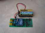
Monitoring and controlling relative humidity is important for humans health. Too low or too high humidity feels uncomfortable, but most importantly high moisture is a factor for growing mold in your home, which could be health threatening (according to EPA and CDC). I will not go into details on how to control humidity. Instead I’ll describe what motivated me to design and create my own temperature and humidity sensor which reports its readings every minute to a central Linux server.
The main requirements for my design were the following:
Affordable price, as I wanted to install four sensors.
Great accuracy both for temperature and humidity readings.
Over-the-air communication, as I wanted to be able to install a sensor even in my bathroom, where I can’t run data or power wires. Support for wired communication too, so that we can reduce the overall price by not installing the wireless module.
Data logging to a computer, because both temperature and humidity change with time, for example when you sleep in the room, and you can’t look at a mechanical temperature or humidity meter every minute, in order to write down the results.
Battery operated, in order to avoid any wiring.
Open-source hardware and software toolchain, so I chose Atmel AVR microcontrollers. I got sick of Microchip and their commercial C compilers.
To have fun with electronics but at the same time create the device as fast as possible, as free time turned out to be a pretty limited resource recently.
I managed to accomplish most of the requirements I set with two exceptions: the device operates only a month on batteries, and cumulatively I spent almost a week to design, solder, develop the firmware, and test the device. Now all the sensors operate from a wall-plug power adapter, and my hunger for environmental control in my house is satisfied.
I’ll now try to describe the whole process and the reasons behind my engineer decisions. Note that I’m an amateur hobbyist.
Idea and requirements
I wrote down all my thoughts in a text editor. Then re-designed all the sticky notes into requirements, and did so a few more times, in order to finally decide what I want to design and not get distracted by new random ideas in my head.
Power supply
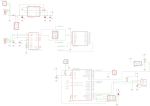
I wanted the device to be able to operate both via USB, and thus be powered by 5V, as well as to be powered by an accumulator or a battery with an input voltage up to 12V, so that it could be used in a car too. I put a polarity protection diode D1 in series with the power line, so that an accidental polarity mismatch doesn’t burn out the power regulator. Such a protection diode must have very low voltage drop and thus low power loss, and the Schottky diode 1N5819 seemed like a good match.
Operating from a battery also means that the voltage regulator must be extremely efficient and with a low bias current consumption, which means that it should draw almost nothing while there is nothing connected to it at its output as a load. Most battery operated devices “sleep” during most of their life cycle, so their consumption is close to zero. I used the ultra low-dropout fixed voltage regulator LP2986-33, marked as U1 in the schematics. The whole circuit operates at 3.3V because of the XBee wireless modules, and also because operating at a lower voltage usually gives lower power consumption.
Since we can have two different power sources, there must be a way to choose which one is active. You can switch between the power sources using the PWR_SELECT jumpers.
Wired communication via USB
I wanted to have the option to use the sensors by directly connecting them to a computer. This way we could save the money for an XBee wireless module. I used the classical USB-to-Serial solution FT232R, which is also quite inexpensive and requires almost no external components. You can see it in the schematics as U2. Note that the I/O lines of FT232R must be configured to operate at 3.3V too. This is done by connecting pin 17, which is the internal 3.3V regulator of FT232R, to pin 4. The internal 3.3V regulator is not used for anything else, and in theory I could have powered the I/O lines, pin 4, directly from the main voltage regulator U1.
Wireless communication
The XBee modules is something I wanted to play with for a long time. They seem very easy to work with and are packed with all kind of features. Though in my case I’m not using almost any of them, not even the AES encryption which could secure the data channel. I’m using the Series 1 XBee low-power embedded RF modules (XB24), which have a power of 1 mW and 30 m indoor range. There are many comments in Internet that the indoor range of the XBee modules is poor and I can confirm that. The range really depends on what the signal must travel through. Sometimes you lose the link even through one wall, sometimes it can go through a few walls. The XBee & XBee-PRO OEM RF Module Antenna Considerations is a great article by the XBee manufacturers. After all, probably by using such a low-power module, we shouldn’t expect so great results. It works well in my apartment though — all rooms report to the central XBee module successfully. On the server’s side, the receiver, I first had an XBee with chip antenna, which I replaced with an XBee-PRO with whip antenna. This made no difference.
Wiring the XBee module is very easy. It requires no external components. If you read the PDF datasheet, you’ll see how many great features an XBee has. I’m using only three of them:
Sleep mode — the microcontroller puts the XBee to sleep by controlling the SLEEP_RQ pin 9.
Networking addressing — each XBee is configured with a unique address, so that the receiver on the server side knows which reading belongs to which sensor probe.
API operation — the receiver XBee module operates in an API mode, which is a frame-based protocol that provides greater flexibility and more control. For example, besides the received data payload, an API frame gives information about the sender’s address and the signal quality.
Temperature and humidity sensor
I wanted to interface the sensor directly using a digital protocol, so that we can minimize the ADC stuff and errors. The SHT11 turned out to be the sensor I was looking for:
Relative humidity accuracy: +/- 3% in the range 20% to 80% RH. The sensor comes fully calibrated.
Temperature accuracy: +/- 1.5 degrees Celsius in the range -15 to +65 degrees Celsius.
Digital two-wire interface.
Very low energy consumption: 80uW (at 12bit, 3V, 1 measurement/s).
The SHT11 is a bit pricey but works very easily and accurately out of the box, so I decided to go with it. There is a very good alternative at Sparkfun — the RHT03 humidity and temperature sensor (also known as “RHT-22”). There were some contradictive comments by Sparkfun users — some say it works very well, some doubt its accuracy. I haven’t tried it but have left space JP7 on the current board, so that at some later time I could solder one RHT03 and use it with the existing schematics.
One note about the SHT11 two-wire interface. Definitely use a pull-up resistor on the DATA wire, as advised in the PDF! I tried to do some magic by the microcontoller and failed. With the exception of the pull-up resistor, everything else worked with no other problems with the SHT11 sensor. The manufacturer Sensirion provides Sample code for the SHTxx sensors which turned out to be very useful. I was able to re-code it for the AVR GNU C compiler in a couple of minutes.
The CRC calculation got me a bit confused. There are multiple different ways to calculate a CRC checksum, and they all provide different results. Each CRC calculation depends on the selected CRC polynomial, which is something like a bit-mask that defines the algorithm for the CRC calculation. After lots of struggle, I finally found an excellent Online CRC Calculation web wizard, which also includes a hardware implementation example, and sample C and VERILOG implementations, which you can copy-paste in your program. Thank you Kay Gorontzi!
Microcontroller
Initially I worked with ATmega8. Then I switched to ATmega168 because of the much lower power consumption. I could have used any other Atmel AVR microcontroller which has USART, internal oscillator, and sleep mode. Though ATmega8 or ATmega168 are always available in my local electronics shop, so I chose one of them. Besides the lower power consumption, ATmega168 has one other major advantage for my application — the watchdog timer can wake the chip from sleep mode and directly execute an interrupt, thus not re-starting the program from the very beginning.
Firmware
I’m working on Windows 7 64-bit and used a USBasp programmer to download the code into the microcontroller. The whole development toolchain is packaged into the WinAVR suite. It includes the AVR GCC compiler and the avrdude programmer. I also downloaded a sample Makefile which makes compilation and firmware download easy.
The main loop of the program does two tasks — measures and displays the readings over the serial port (which goes to the USB or over-the-air via XBee), and sleeps for about 60 seconds. As already mentioned, I use the new feature of ATmega168 which allows for the Watchdog timer to generate an interrupt, which wakes the chip from sleep mode. This is very handy as it allows you to continue the program at the point where you put it to sleep. The sleep mode was something new for me; there are some URLs in the source code which show what online articles helped me to master it. Note that the XBee RF transmitter is also put into sleep mode, in order to save battery.
Data collector
All the sensor readings are collected to a Linux server over-the-air. I use an XBee Explorer USB by Sparkfun to connect the XBee receiver with the Linux server. The XBee is seen as a serial device on the Linux box. The frame protocol of the XBee API is easy to understand and I implemented a Perl script to parse it. Here is a sample reading which is received from one of my wireless sensors (0x0001 is the address of the probe standing outside of my apartment):
[Mon Dec 26 17:32:11 2011] RX_packet: source=0x0001, rssi=-55dBm (opt=0x00): 4.24;69.04
As you can see, now it’s winter here — 4.24 degrees Celsius temperature; 69.04% relative humidity (RH).
Board design
Both the schematics and PCB board were designed using Eagle PCB by CadSoft. This is a great piece of software. Most PCB factories accept Eagle board files directly. You’ll find my Eagle files in the Resources section at the end of this article.
Lessons learned
There are a few things which I discovered only once I already built and tested the schematics:
Battery-operated devices are hard to design — in theory my sensors were supposed to last for about 3 months with a 9V battery. In practice only one of them lasted for a month, the others – for a week.
Electronics components, boards and/or assembly could differ a lot — see above. Also one of the SHT11 sensors is sometimes giving CRC errors.
XBee indoor range is not excellent.
Research and development takes a lot of time, usually 2x or 3x the time you planned. Furthermore, building something with love takes even more time, but in the end it pays off with great results and satisfaction.
You can create an electronics device with a lower price than what is currently offered on the marked. But this has its price too — your time, and you get no guarantee whatsoever.
I had different plans for this blog article but it got so lengthy that I wrote it in four different days (and it’s Christmas now). The main idea was to sketch the device and all its components, and to show that they can work together as a finished product. If there is any interest by other people, I’m happy to answer to any questions.
Windows 7 and Linux live together on the same hard disk in perfect harmony. I had Windows 7 installed first, and a few GBytes of free space at the end of the hard drive which I left unpartitioned. Here is how to install Ubuntu:
Boot from the CD, and install it. Make sure that you choose an empty partition, and also make sure that you select to install the boot loader on the Linux partition (example: on “/dev/sda3”, and not on the main MBR “/dev/sda”).
Until here you have an Ubuntu installation which you cannot boot, yet.
Here is how to configure the Windows 7 boot loader to include Ubuntu in the boot choice menu:
Download EasyBCD and install it. EasyBCD is free for non-commercial use and offers a nice GUI to edit the Windows 7 boot loader menu.
Do the following in EasyBCD — Add New Entry -> Operating Systems -> Linux/BSD:
Type: GRUB 2
Name: Ubuntu
Device: (Automatically configured)
Finally, click on “View Settings” in EasyBCD. You should see something similar to the following:
EasyBCD ships the “stage1” boot loader of GRUB2 (\NST\AutoNeoGrub0.mbr), so you don’t have to do anything else. Just reboot your Windows 7, and the boot menu should present a choice between “Windows 7” and “Ubuntu”.
A note of caution: It is highly recommended that you do a backup of your whole hard disk before you try to install Ubuntu or modify the boot loader options.
P.S. There is no “boot.ini” in Windows 7. You could modify “boot.ini” in Windows XP to achieve the same result, but this does not apply for Windows 7.
I want to share my outstanding experience with Intel when I wanted to return my failed Intel X-25M SSD hard drive. The disk was purchased on Mar/2009 from Amazon, and Intel claim a 3-year limited warranty for this model. So I was almost at the end of the warranty. Here is a timeline of the actions:
Mon, 24/Nov/2011: First I contacted Amazon, because this is what Intel’s policy states — contact the OEM provider first. Amazon directed me to contact Intel directly, so I sent them an e-mail.
Tue, 25/Nov/2011: 24 hours passed and I got no reply, so I decided to try the Chat support by Intel. I had to wait until it was North America work hours time; before that Chat support was unavailable. My chat with the US chat support representative was quite unhelpful — they stated that they have no idea which support center is handling my request, because I am from Europe, and they are the North America support center. So I had to wait for an e-mail reply, or try to call the EMEA support centers by phone. It was late at night here in Europe, so I decided to wait.
Wed, 26/Nov/2011: Got reply by e-mail from the EMEA support center. We exchanged some e-mails.
Thu, 27/Nov/2011: Some more tips and communications with the EMEA support member. They finally decided that I won’t be able to fix the SSD drive myself, and it should be replaced. I received a Standard Warranty Replacement (SWR) order number along with instructions on how to send the defective SSD disk to Intel.
Fri, 28/Nov/2011: I shipped the SSD drive via DHL, as instructed. The DHL delivery was paid by Intel!
Mon, 31/Nov/2011: DHL delivered the package to the RMA center of Intel. It took 3 days.
Tue, 1/Oct/2011: Intel shipped back a package via DHL.
Wed, 2/Oct/2011: DHL delivered the package to me. It took 1 day — it seems that Intel used an express DHL delivery option!
I received a brand new SSD drive of the same model and size, and Intel kept me as a 100% satisfied customer! 🙂
Suppose you have one or more network interfaces, and they have one or more assigned IP addresses, also called aliases. If you need to find out which IP address and interface will be used as a default “source” by your Linux box, you need to execute the following:
ip route get 8.8.8.8
This, of course, assumes that 8.8.8.8 is not directly connected on your networks somehow. Since this is one of the Public Name Servers of Google, I think it is safe to assume so.
The output is pretty much self-explanatory — the route to “8.8.8.8” will originate from device “eth0”, the used source IP address will be “10.0.2.15”, and the next hop, the (default) gateway, will be “10.0.2.2”.
This method is 100% reliable. The man page of “ip” says that “this command gets a single route to a destination and prints its contents exactly as the kernel sees it”.
I recently needed to escape some user-supplied input for an URL address variable, in a Bash script. This is what the PHP urlencode(), and Perl URI::Escape::uri_escape() functions do, for example. My initial approach was to call Perl from the Bash script:
Though I wanted to optimize the Bash script by not having to fork() a Perl interpreter every time, which could be CPU intensive if you execute the Bash script often. So I ended up with the following solution, entirely coded in Bash, using Bash string manipulation and Bash hash arrays:
The logic works pretty well, but the performance is terrible. It turned out that the Bash string manipulation methods are rather slow. So I finally ended up by using Perl, the same way I did it initially. For very small strings in the order of a few characters, you should be fine. But for anything else, this implementation is not recommended.
If you still want to use the Bash code, please download it directly from here, because the blog page messed up some of the special ASCII characters.
I just found out how to make my Google Sites backup script almost non-interactive, so I decided to share. My usage pattern of this script is that I run it every month in the Linux console, and then the weekly backup of my hard disk takes care to additionally back up the information.
Why bother backing up Google Sites?
While Google are very reliable and probably they will never fail me here, I want to have an offline backup of my Google Sites pages in case someone steals my Google Account. So I back up. Online and offline, every week.
The backup script uses the wonderful free Java application “Google Sites Liberation“. My script is actually more like a sample Bash usage of this Java tool. You need to download the .jar file and store it in the same directory as the backup script. The source code follows:
#!/bin/bash
set -e
set -u
set -o pipefail

trap 'echo "ERROR: Abnormal exit." >&2' ERR

# config BEGIN

GUSER='username@gmail.com'
WIKI_LIST='wiki1 wiki2 wiki3'
JAR_BIN='google-sites-liberation-1.0.4.jar'
ROOT_BACKUP_DIR='./sites.google.com'

# config END

echo "We are using '$JAR_BIN'. Check for a newer version:"
echo '	http://code.google.com/p/google-sites-liberation/downloads/list'
read

echo "The directory '$ROOT_BACKUP_DIR' will be deleted!!!"
echo 'Press Enter to confirm.'
read

rm -rf "$ROOT_BACKUP_DIR"
mkdir "$ROOT_BACKUP_DIR"

echo -n "Enter the password for '$GUSER': "
read -s -r -e PASS
echo ; echo

for wiki in $WIKI_LIST ; do
	BACKUP_DIR="$ROOT_BACKUP_DIR/$wiki"
	echo "*** Exporting '$wiki' in '$BACKUP_DIR'..."
	echo "Press Enter to continue."
	read

	mkdir "$BACKUP_DIR"
	java -cp "$JAR_BIN" com.google.sites.liberation.export.Main \
		-w "$wiki" \
		-u "$GUSER" \
		-p "$PASS" \
		-f "$BACKUP_DIR"
	echo
done
There is one specific hack here. Since XML allows it to have an element with the same name multiple times on the same subtree level (see <item> on lines #05, #06, #08, #09), and at the same time it does not allow to have an element with only numeric name, we need to make the following exception for arrays which have numeric indexes:
If an element is named <item>, and it has an attribute named “idx”, then we will use this attribute as name, and respectively array key.
This is handled in the XmlCallback() class, method startElement(), lines #44, #45, #46, which are also highlighted. You can see the sources at the end of the article.
XML also allows it that an element contains both DATA and sub-elements. This cannot be parsed into a PHP array, and will result in an Exception.
The parsed PHP array would look like as follows:
Array
(
	[root] => Array
	(
		[first_item] => Test 1st item
		[first_level_nested] => Array
		(
			[0] => value #1
			[1] => value #2
			[second_level_nested] => Array
			(
				[0] => value #3
				[1] => value #4
			)

		)

		[second_item] => Test 2nd item
	)

)
If you liked the results, you can download the sources which follow (click “show source” below):
<?php

function xml_decode($output) {
	$xml_parser = xml_parser_create();
	$xml_callback = new XmlCallback();

	if (!xml_set_element_handler(
		$xml_parser,
		array($xml_callback, 'startElement'),
		array($xml_callback, 'endElement')
	)) throw new Exception('xml_set_element_handler() failed');
	if (!xml_set_character_data_handler($xml_parser, array($xml_callback, 'data'))) {
		throw new Exception('xml_set_character_data_handler() failed');
	}
	if (!xml_parser_set_option($xml_parser, XML_OPTION_CASE_FOLDING, 0)) {
		throw new Exception('xml_parser_set_option() failed');
	}

	if (!xml_parse($xml_parser, $output, TRUE)) {
		$xml_error = sprintf(
			"%s at line %d",
			xml_error_string(xml_get_error_code($xml_parser)),
			xml_get_current_line_number($xml_parser)
		);
		throw new Exception("XML error: $xml_error\nXML data: $output");
	}

	xml_parser_free($xml_parser);

	return $xml_callback->getResult();
}

class XmlCallback {
	private $ret = null;
	/* assign and use references directly to the array, or else you'll be in trouble */
	private $ptr_stack = array();
	private $level = 0;

	public function __construct() {
		$this->ptr_stack[$this->level] =& $this->ret;
	}

	public function startElement($parser, $name, $attrs) {
		if ($name == 'item' && isset($attrs['idx'])) {
			$name = $attrs['idx']; /* reconstruct arrays with numeric indexes */
		}

		if (!isset($this->ptr_stack[$this->level])) {
			$this->ptr_stack[$this->level] = array();
			$this->ptr_stack[$this->level][$name] = null;
		} else {
			if (!is_array($this->ptr_stack[$this->level])) {
				if (!strlen(trim($this->ptr_stack[$this->level]))) {
					/* if until now we got only whitespace (thus scalar data),
					but now we start a nested elements structure, discard this
					whitespace, as it is most probably just space between the
					element tags */
					$this->ptr_stack[$this->level] = array();
				} else {
					throw new Exception('Mixed array and scalar data');
				}
			}
			if (isset($this->ptr_stack[$this->level][$name])) {
				/* isset() == (isset() && !is_null()) */
				throw new Exception("Duplicate element name: $name");
			}
		}

		/* array_push() */
		++$this->level;
		$this->ptr_stack[$this->level] =& $this->ptr_stack[$this->level-1 /* MINUS ONE! */][$name];
	}

	public function endElement($parser, $name) {
		if (!array_key_exists($this->level, $this->ptr_stack)) {
			throw new Exception('XML non-existing reference');
		}

		/* array_pop() */
		unset($this->ptr_stack[$this->level]);
		--$this->level;

		if ($this->level < 0) throw new Exception('XML stack underflow');
	}

	public function data($parser, $data) {
		if (is_array($this->ptr_stack[$this->level])) {
			if (strlen(trim($data))) { # check if this is just whitespace
				throw new Exception('Mixed array and scalar data');
			} else {
				/* we tolerate AND skip whitespace, if we're already in
				a nested elements structure, as this whitespece is most
				probably just space between the element tags */
				return;
			}
		}
		if (is_null($this->ptr_stack[$this->level])) {
			$this->ptr_stack[$this->level] = ''; /* first data input */
		}
		$this->ptr_stack[$this->level] .= $data; /* we may be called several times, in chunks */
	}

	public function getResult() {
		return $this->ret;
	}
}
Update, 20/Jul/2011: The source code was modified to handle white-space better, in order to fix the following tricky sample XML input: <item6> & < </item6>
Update, 30/Jul/2011: Another bugfix which handles empty responses like: <response/>
References:
There are plenty of other (similar) solutions out there:
PHPUnit has a built-in method to test if an expected exception occurred during a test case:
$this->setExpectedException('Exception');
You cannot however test the message of the exception. There are cases where a program may throw the same exception type, but with different messages for different errors, and you want to differentiate between them.
Here is my example code on how to reliably test for the type and message of an exception:
class staticSessionTest extends PHPUnit_Framework_TestCase {
	...
	function test_bad_data() {
		$emess = null;
		try {
			$this->sess->start('must be array', FALSE, FALSE); # we expect an Exception here
		} catch (Exception $e) { $emess = $e->getMessage(); }
		$this->assertEquals($emess, 'Session data must be an array');
	}
	...
}
Putting the assertEquals() outside of the try…catch block ensures that you cannot forget to test for the message. The type of the exception is coded inside the catch(…) block.
UPDATE: I just re-read the latest PHPUnit Annotations, and this feature is already included in the standard PHPUnit suite. The difference between my custom code and the “@expectedExceptionMessage” annotation is that the annotation is valid for the whole test block of execution, while using try…catch you can specify precisely where you expect the exception to occur.
")


")
